
Since this is our first foray into the world of the electron, I thought I’d introduce you to Professor Science ( I have no idea if that’s his name); The mascot of the kit’s manual. He’s presumably an anthromorphized version of an earlier version of the kit, judging from his wood frame. I will not be showing any full screenshots of the manual, as it is likely still protected by copyright; Instead, I’ll draw the schematic we’re going to build on some graph paper. Both the paper, and the mechanical pencil I’m using belonged to my late grandfather, who was an engineer. I will quote liberally from the manual when it is entertaining or interesting, of course. So let’s start with our first circuit’s diagram:

So, the manual insists that, as they’ve arranged the projects into categories, you might want to consider doing them in order, so you can stack knowledge from one into the next. Why, then, are we on Page 20, Circuit #24 for our first go? Well, The first 23 circuits are under a heading ‘Surprise and Game projects’, and are all pretty complex. It seems they put those there as a hook. Circuits 24 through 59 are under ‘Back To The Basics’, so we’ll be starting with those.
Anyway, let’s explain what’s going on in this diagram. The straight lines represent conductors; wires, if you will. On the left, you can see a sort of curve inside a little dome shape. That’s the symbol for an incandescent lamp; those are the ‘old’ kind of light bulb, with a filament inside. The lamp then goes to the negative terminal of a battery. The symbol for a battery is derived from a drawing of the earliest sort of battery, a voltaic pile. Voltaic piles are named after Alessandro Volta , an Italian physicist born in 1745. The volt, a unit of electric potential, is named after him, too. The positive terminal of the battery goes ’round to one terminal of a switch, a device that can break an electrical circut, You can see how there’s a gap between that and the bent line that represents the mechanism of the switch. The other terminal of the switch then finds it’s way back around to the lamp. This is a recurring theme, most circuits need to be a closed loop. The electricity needs to have a path all the way ’round. That is, after all, what the switch does, interrupt that path.
So, let’s build it:
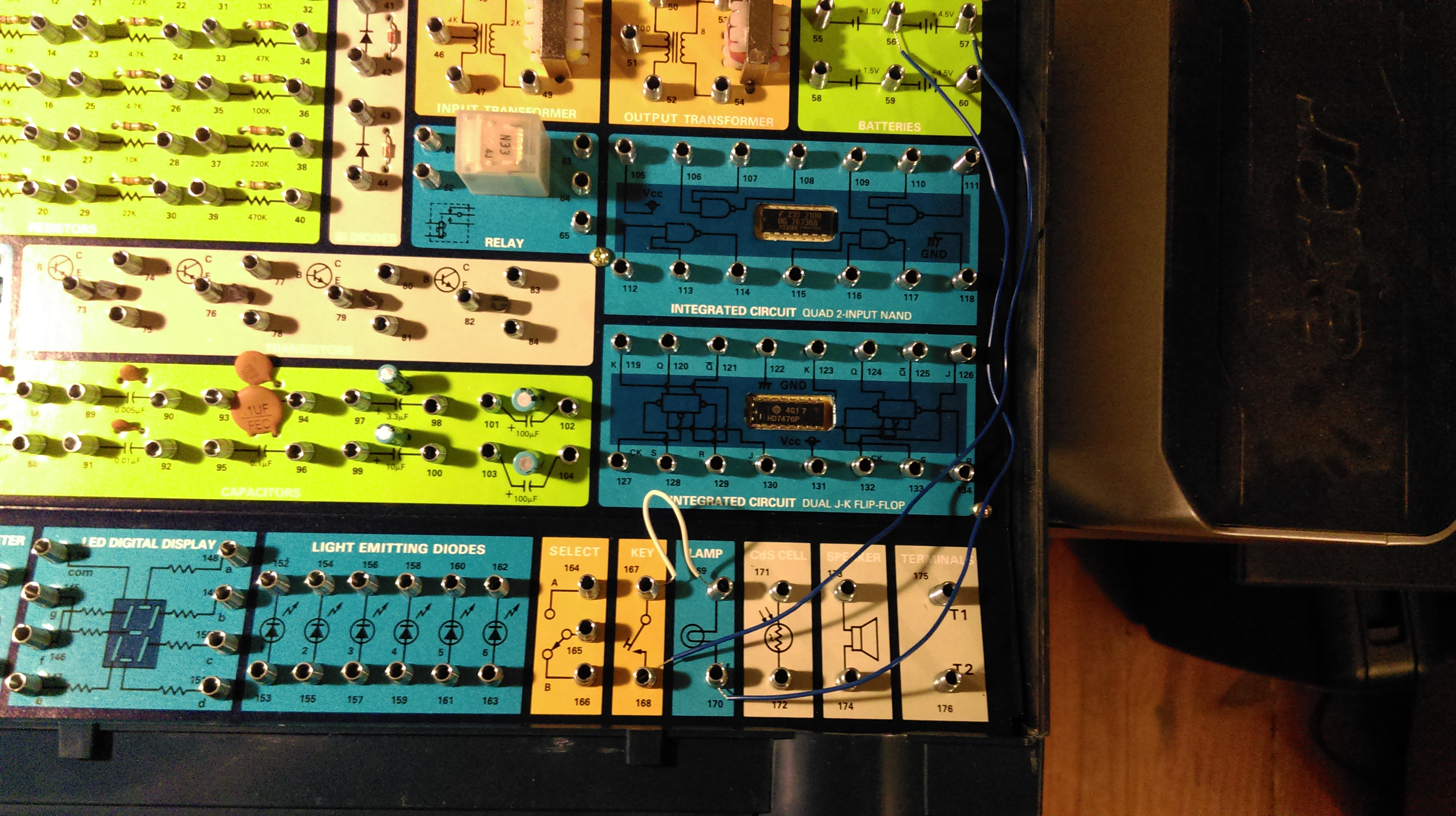
Clearly, I need to work on my photo skills before I do the next circuit! So, the two blue wires coming from the top down the right side, those go to the positive and negative terminals of the battery. One goes to a terminal on the lamp, one to a terminal on the switch, then the other terminal of the switch has a little white wire that goes to the other lamp terminal. As an side, that’s one of the few things I don’t like about this kit. The wires are color-coded by length; It would be preferable to have different colors of wires of each length, so you could color code your circuits as you built them; That being said, then the kit would have to come with many more wires, and would have been much more expensive. It would be an easy third-party ‘hack’ to use ‘properly’ colored wires.
So, what’s it do?
When I press the switch (a momentary switch, or ‘key’), it completes the circuit. Current flows from the battery, through the lamp. The filament inside the lamp has a good bit of resistance, that is, it opposes the flow of the current through it. The current trying to force its way through the filament causes it to become very hot. When a hot body (*giggle*) is at the right temperature, it will emit some of that energy as visible light. This is incandescence. Incandescent light bulbs emit only a tiny fraction of their radiated energy as visible light; the rest comes off as infrared radation, which we feel as heat. This is why these bulbs are so inefficient.
The book points out that the current flow actually goes from negative to positive, not positive to negative as was originally thought. If you read the earlier link about current, you’ll see it’s a bit more complicated than that. . . Of course it is! We’re actually dealing with particle physics here. For simplicity’s sake, for now, we’ll just stick with the standard electrical engineering convention of positive, negative, and the way current flows.
So what’s the deal with voltage and current? Current is a flow of electric charge, often carried by moving electrons in a wire. Voltage is a measure of electrical potential, or tension; That is, the “electric energy charge difference of electric potential energy transported between two points.” More simply, it’s a way to measure the potential work a given charge can do, think of it like water pressure, in a way. Using water to think about electricity is an analogy called the hydraulic analogy. Like any analogy, it’s not perfect, and if taken too far can give the wrong idea about how electricity works. So we’ll try not to go too far!
So, that’s our first circuit. I’ll do another tomorrow!
