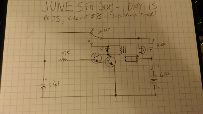
Today’s circuit continues the capacitor theme. It’s a fairly complex circuit, with a lot of componentry we’ve not actually had formal explanation for yet (though we’ve seen all of it already), but it works pretty well. I would say it’s basically a combination of Day 12’s ‘Quick Capacitor’, and Day 10’s ‘Capacitor Timer’; it shows a capacitor in a timing circuit that actually works well, as opposed to the one from Day 10. Here’s the circuit:
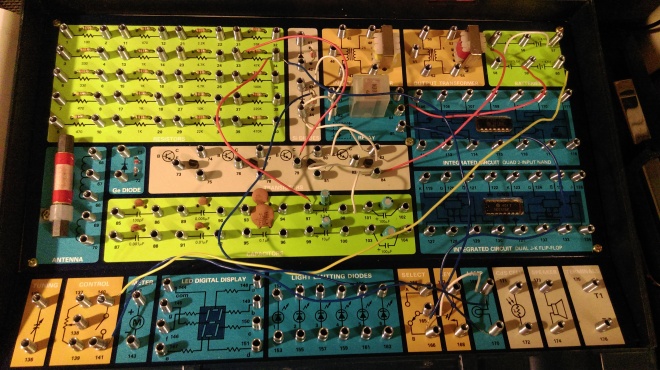
So we have the select switch, a 3.3 microfarad capacitor, a 47 kilohm resistor, not one but -two- transistors, a diode, a relay, a lamp, and batteries. The resistor is protecting the transistors from too much current, the diode is making sure that the current only flows across the control terminals of the relay in one direction. The transistors are, from what I can gather, acting together to allow current to flow to the relay when they receive a charge from the capacitor. If you observe the select switch, with it set in ‘B’, the capacitor charges, but current cannot flow from it to the relay or to the upper leg of the upper transistor. With it set to ‘A’, current from the batteries does not charge the capacitor, but if the capacitor is charged, current from it should flow through the transistors, which should send a signal current to the control terminals of the relay, switching it on, which should supply current to the lamp, until the capacitor discharges, causing the relay to turn back off. Let’s look at it all wired up, and then give it a go:
Okay, so here’s how it works:
We start with the circuit set to ‘B’. After a moment or two, I flip the selector to ‘A’. The relay clicks, the lamp lights, and it remains lit for awhile, then the relay clicks off and the lamp turns off. I imagine by changing the type or size of the capacitor, you could change the duration the lamp remains lit. I did experiment with leaving the circuit in ‘B’ longer, and noted that the longer I did so, the longer the lamp stayed lit, to a point, anyway.
Interestingly enough, when doing this circuit, I found an error in the original kit documentation. When I first built it, it worked backwards. That is, with the switch set to ‘B’, the lamp stayed lit. When I flipped the switch to ‘A’, the lamp turned -off-, and stayed -off- for awhile before turning on. After puzzling over this for a few minutes, I found that the kit documentation had me attach the lamp to the wrong relay switched terminal; the one that’s live when the relay is -off-; so the lamp defaulted to on. When the capacitor was charged and the circuit in ‘A’, it was turning the relay on as intended, which turned the lamp off. Oops.


