I’ve definitely not given up on this project, but I’m going to have to extend the hiatus before I can resume normal updates. Several of the computer systems I used ’round the lab have decided to have issues all at the same time, so I’ve been spending my free time repairing them instead of updating this blog. I will endeavour to continue as soon as humanly possible.
Month: June 2015
Extended Intermission
Due to some weather factors and some further equipment issues, the intermission unfortunately got extended through Sunday June 7th. Barring further complications, I plan to resume the normal circuit blogging on Monday June 8th.
Ooops
Sorry all, no circuit was posted for Saturday June 6th; I got sidetracked with some computer maintenance. A circuit will be posted sometime today, Sunday June 7th.
Day Thirteen – Electronic Timer
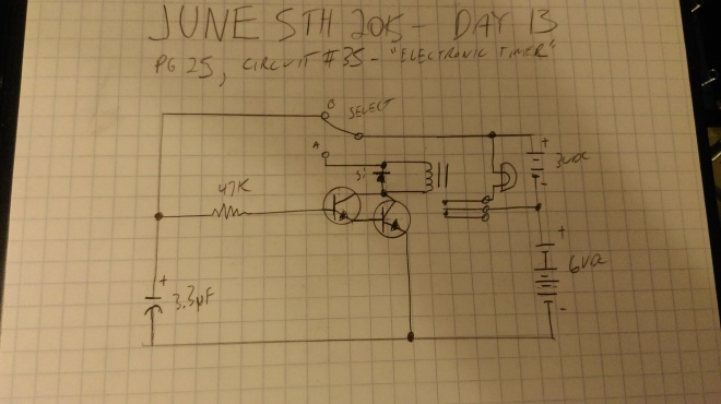
Today’s circuit continues the capacitor theme. It’s a fairly complex circuit, with a lot of componentry we’ve not actually had formal explanation for yet (though we’ve seen all of it already), but it works pretty well. I would say it’s basically a combination of Day 12’s ‘Quick Capacitor’, and Day 10’s ‘Capacitor Timer’; it shows a capacitor in a timing circuit that actually works well, as opposed to the one from Day 10. Here’s the circuit:
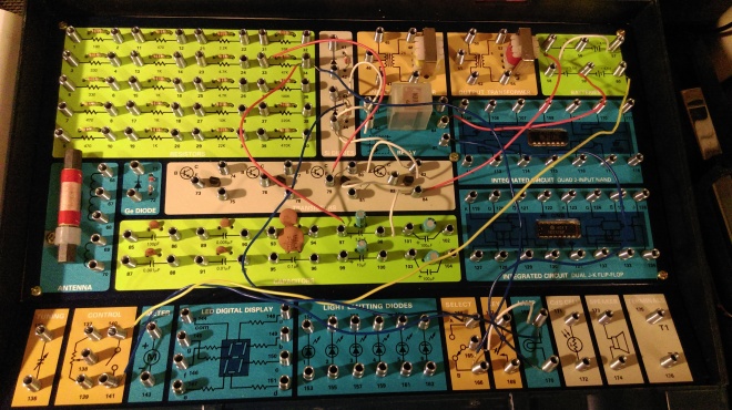
So we have the select switch, a 3.3 microfarad capacitor, a 47 kilohm resistor, not one but -two- transistors, a diode, a relay, a lamp, and batteries. The resistor is protecting the transistors from too much current, the diode is making sure that the current only flows across the control terminals of the relay in one direction. The transistors are, from what I can gather, acting together to allow current to flow to the relay when they receive a charge from the capacitor. If you observe the select switch, with it set in ‘B’, the capacitor charges, but current cannot flow from it to the relay or to the upper leg of the upper transistor. With it set to ‘A’, current from the batteries does not charge the capacitor, but if the capacitor is charged, current from it should flow through the transistors, which should send a signal current to the control terminals of the relay, switching it on, which should supply current to the lamp, until the capacitor discharges, causing the relay to turn back off. Let’s look at it all wired up, and then give it a go:
Okay, so here’s how it works:
We start with the circuit set to ‘B’. After a moment or two, I flip the selector to ‘A’. The relay clicks, the lamp lights, and it remains lit for awhile, then the relay clicks off and the lamp turns off. I imagine by changing the type or size of the capacitor, you could change the duration the lamp remains lit. I did experiment with leaving the circuit in ‘B’ longer, and noted that the longer I did so, the longer the lamp stayed lit, to a point, anyway.
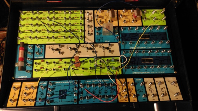
Interestingly enough, when doing this circuit, I found an error in the original kit documentation. When I first built it, it worked backwards. That is, with the switch set to ‘B’, the lamp stayed lit. When I flipped the switch to ‘A’, the lamp turned -off-, and stayed -off- for awhile before turning on. After puzzling over this for a few minutes, I found that the kit documentation had me attach the lamp to the wrong relay switched terminal; the one that’s live when the relay is -off-; so the lamp defaulted to on. When the capacitor was charged and the circuit in ‘A’, it was turning the relay on as intended, which turned the lamp off. Oops.
Intermission – Thursday, June 4th.
There will not be a circuit posted today, as I am exhausted. Normal circuiting will resume tomorrow, Friday, June 5th.
Day Twelve – The Quick Capacitor
Today’s circuit continues the theme of exploring the behavior of capacitors. A relatively simple circuit, with two 100 uF capacitors in parallel and no un-introduced componentry. It’s meant, I suppose, to be a contrast to day 10’s “Capacitor Timer”, showing how quickly capacitors can charge and discharge. It works much better than that circuit though. Here it is:
So, we can see batteries, divided into a 3VDC supply and a 6VDC supply. A select switch, the two parallel capacitors, a relay, and a lamp attached to the switching side of the relay. Here it is in the figurative flesh:
So what’s it do? Note that I start the project with the selector on ‘B’. The kit manual suggested this:
I flip the selector to A, the lamp flashes. I flip it back to B, the lamp flashes, and so on. So what’s going on here? With the selector set in B, the positive side of the capacitors is shorted to the negative battery terminal of the 6VDC battery set; if you follow the circuit, the -negative- terminal of the capacitors is attached to the same terminal; so with the switch in this position, no current flows into the capacitors to charge them. When I flip the switch to A, current can charge the capacitors. The lamp also flashes, because the current also toggles the relay, turning the power to the lamp on. It’s a brief flash because once the capacitors begin to charge, they interrupt the flow of current to the relay and it turns back off. Flipping the switch back to B causes the capacitors to discharge, flashing the lamp briefly again. So, you see that capacitors can charge and discharge quickly.
Day Eleven – Light Dimmer
Today’s circuit bares a lot in common with the previous two. Like yesterday’s circuit, it uses a transistor as a kind of switch. Structurally, though, it has more in common with day nine’s circuit. It uses an LED as an indicator, and it is demonstrating properties of capacitor charge. Let’s have a look at it.
So, there’s a 100 microfarad capacitor, a 100 kilohm resistor, select switch, power switch, 9VDC of batteries. Then the center part of the circuit, we see the transistor, a 330 ohm resistor, and the LED. With the select switch on ‘A’, the battery power does not flow directly through the 100 kilohm resistor and the 100uF capacitor, instead, it must flow through the transistor to get there; Sometimes, a transistor can work as a diode, and block the flow of current. As you’ll see in a moment, that’s what happens in this circuit. With the select switch on ‘A’, current can flow through the 100 kilohm resistor and charge the 100uF capacitor. What happens then? What does the transistor do? What else happens? We’ll see. First, here’s what things look like all wired up:
Ok, let’s see what happens:
When the power is turned on with the selector in ‘A’, the batteries gradually charge the capacitor, as they do, it can begin to then release enough current to tell the transistor to switch current to the LED, which glows brighter and brighter as more current flows. When I then flip the selector to ‘B’, the capacitor gets no more charging current. For a good while, it still provides enough power to the transistor to keep the LED lit. Eventually, the capacitor’s charge fades too much, and the LED goes dark. So this circuit demonstrates fairly well the fact that capacitors can discharge slowly.
Day Ten – Capacitor Timer
This is another one of those circuits I wasn’t too happy with; there are a lot of those with the way this kit does things, it seems. I can understand the logic: Just dive in, and we’ll fill in the missing bits later. For now, just build the circuit and have fun. I’m just not that sort of personality, I guess. I’d prefer to have any component we’re going to use explained to me first. Still, though, I suppose that’s part of the experience. Here’s today’s circuit:
We’ve got two 100uF capacitors, wired in parallel, A 22 kilohm resistor in parallel with those, a 10 kilohm resistor, a 4.7 kilohm resistor; To the right of the 10 kilohm resistor is a component we’ve not talked about yet; the kit book makes no mention of it or what it’s doing. It’s the symbol that looks like a triangle with a line underneath it. That is a diode; A diode is a component that conducts current in only one direction; Ideally, it has zero resistance in one direction, and infinite resistance in the other. (In reality, this isn’t true, but it gives you an idea of how it works.) Diodes have many uses, especially when you want to control the flow of current so that it goes in only one direction. I suspect that this one is being used for over-voltage protection, that is, to keep too much current from flowing into the component the diode’s bottom terminal is connected to; One we’ve seen before when the kit went off into la-la land, the transistor, remember, that’s the symbol that’s the circle with the network of lines inside it. When we talked briefly about transistors before, we discussed how they can amplify and/or switch electronic signals. I think this one is acting as a sort of switch. Also in the circuit, you see the relay, a power switch, and a 9VDC battery power supply. So, what the circuit is doing is demonstrating that capacitors can take some time to charge. When the power is turned on, the capacitors begin to charge, when they accumulate enough charge, they cause the transistor to act like a switch, sending current to the relay, which clicks. This circuit is using the relay as a noisemaker, like we saw in some earlier circuits. Here’s what it looks like all built:
So, what’s the demonstration like? Here’s a brief video I made of it:
When I turn the switch on, you hear the loud click of the switch, and then almost immediately after, the softer click of the relay. The shortness of the delay makes this circuit even more disappointing. It doesn’t prove to be a great demonstration. Still, though, you get the idea, sometimes capacitors take some time to charge. If you’ve ever used an older camera, where you had to turn it on, and wait a minute or two for the flash to charge (usually punctuated by a high-pitched whining sound from the capacitors in the charging circuit), that’s what was going on. There are scenarios, as you might imagine, where a delay in capacitor charging could be used on purpose, as a sort of timing circuit, as the title of this experiment implies. I’ll leave you with this thought exercise: How could we make the charging take longer? Use higher farad capacitors? add a resistor to limit the charging current? Think about it. Feel free to post your thoughts in a comment.
Day Nine – “The Electronic Gas Tank”
Today’s circuit is dealing with capacitors oncemore, specifically, their ability to store electricity. Capacitors are very good at storing electricity for brief periods, and then releasing it all at once. A camera flash is a good example of where you might find a capacitor doing this sort of work; storing up a charge of energy from the batteries, and then dumping it very quickly to fire the flash. As you’ll see, this circuit works kind of like that. (Capacitors are good for other things, too. The right kind of capacitors in the right kind of circuit can store energy for much longer times, even substituting for a battery. They’re also good at smoothing current out, by storing the spikes and then using that stored charge to fill in the valleys. They have many other uses too!) This circuit does include one component we’ve not been introduced to yet, but that many of you will be at least somewhat familiar with, an LED. An LED, or light-emitting diode is a type of electronic light source that is much more efficient than an incandescent lamp. I’ll hold off on explaining them in detail for now, as we’ve not even been introduced to -diodes- yet. For now, just know that it’s a very efficient source of light. Here’s today’s circuit:
Pretty simple circuit, overall. When the power switch is on, and the select switch is on ‘A’, power flows from the 9VDC battery supply into a circuit of two parallel 100uF capacitors; remember that capacitors in parallel have -higher- capacitance than when in series. With the select switch set to ‘A’, no current flows through the LED; that’s the circular symbol over to the right there. If the selector switch is instead set to ‘B’, no current flows from the batteries into the circuit at all, instead, it flows from the capacitors, through a 1 kilohm resistor (which is there to protect the LED from too much current), through the LED. Here’s what it looks like all wired up:
So, let’s see what it does:
Not much to see with the selector set to ‘A’, and then when I flip it to B, the LED glows brightly for a moment, before dimming to nothing. Sort of like a camera flash, no?
Here’s a thought exercise: If I charge the capacitor longer, will the LED stay lit longer? If so, for how long of a charge time will this hold true? What’s the limit to how much charge a capacitor can hold?


