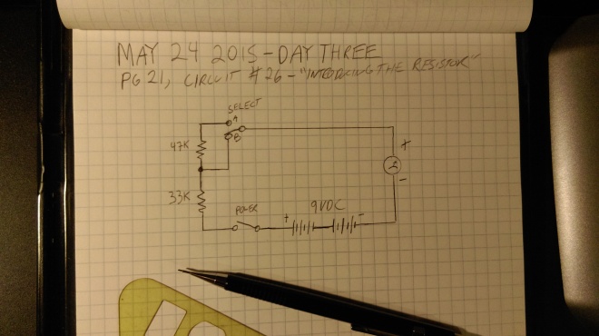
Today’s circuit, introducing the resistor, introduces us to a new component, the aptly named resistor. A resistor is a component that uses the electrical principle of resistance to reduce current flow. Among the things they can be used for is reducing voltages. Here’s today’s diagram:
This simple circuit is introducing us to the properties of resistors, and what they do in series, that is, wired in-line together, one after the other. There’s a select switch, what it’s doing is taking the resistor labeled 47K out of the circuit when the switch is set to ‘B’. The unit of measurement of resistance is the ohm, named after Georg Simon Ohm, a German physicist born in 1789. One of his most important contributions to science is a law known as Ohm’s law, which describes the relationship between voltage and current. We talked about this a bit on day one, and it will come up again. Using Ohm’s law, you can determine things about current from voltage, and things about voltage from current. For now, we’re getting off on a tangent though. The 47K stands for 47 kilohms, the 33K for 33 kilohms. A kilohm is, of course, 1000 ohms. So, other than the resistors and the select switch, we’ve got an on/off switch, a series of batteries supplying 9VDC, and that circular symbol there on the right. That’s the symbol for a meter. So what this circuit is going to do is show us, on a meter, the difference between having our current run through just a 33 kohm resistor, and both a 33 kohm resistor -and- a 47 kohm resistor. Here’s what it looks like all wired up:
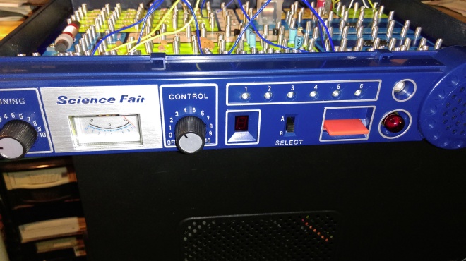
So, let’s set the selector to A, turn the circuit on, and see what the meter does. Remember with the selector on ‘A’, both resistors are in the circuit:
Ok, with the switch on A, the meter swings not quite halfway to the right. So then we switch things to B:
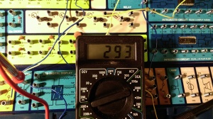
The meter swings all the way to the right. With only one resistor in the circuit, much more current is flowing. To get a better idea of what’s happening, I used my multimeter, a tool that can act as a volt meter, ohm meter, or, as I’m about to show you, an ammeter, measuring the current in a circuit. Here’s the multimeter, set to measure milliamps. (An ampere, or amp, is the SI unit for measuring current. A milliamp is a thousandth of an amp).
Position A:
Position B:
This verifies the earlier results; With both resistors in the circuit, as in position A, the meter shows that 120mA of current is flowing. If only the 33K resistor is in the circuit, 293mA flow.
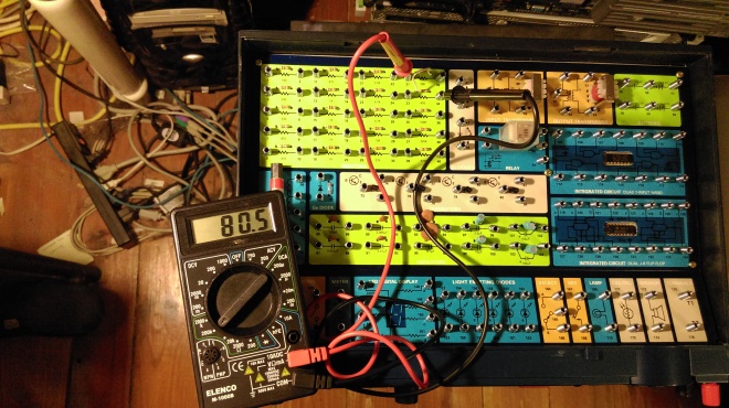
The manual explains when wiring resistors in series, you can add their ohm values together to determine the total resistance of the resistor set. So 33+47=80K. We can verify this by doing a little experiment. We’ll set the multimeter to another setting, one that allows it to act as an ohm meter, that is, a device for measuring the resistance of something. Take a look:
Since the details are a bit hard to see, what I’ve done is attached one probe of the meter to the first terminal on the 33K resistor, then a jumper wire from the second terminal of the 33K resistor to the first terminal of the 47K resistor, then the other meter probe to the second terminal of the 47K resistor. The meter is set to display in kilohms. As you can see, it shows just about 80K.
I’ll leave you with something fun to try. Read about Ohm’s law from the link earlier in this post. Look at the pictures that show the meter measuring milliamps. You know the resistor values are 33K, 47K, and that they add up to 80K. You also know that the batteries are supposed to be supplying 9 volts. Plug these numbers into Ohm’s law, and see what you learn.


